
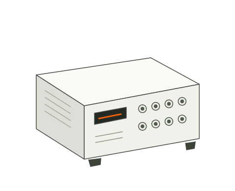
 Concept illustration↗
EQUIPMENT SERIES
T8-3X Dynamic Signal Analyzer
Acquire and analyze vibration, shock, sound pressure, dynamic force, pressure and voltage signals for measurement, structural response and modal-test workflows.
T8-3X
APPLICATION NOTE · T8-DSA-406
After a structure is struck or excited, its response is a gradually decaying vibration. How fast it decays and at what frequency directly affect product quality and service life. This module extracts four core parameters from a measured decay waveform — natural frequency, damping ratio, amplitude and initial phase — and derives more than ten engineering values, including the quality factor, logarithmic decrement, half-power bandwidth and half-decay time.
Strike a tuning fork and the sound fades; strike a structure and the vibration slowly stops. How fast it fades is described by physical parameters that can be measured precisely. The module turns the decay into a parameter table for a report.
Engineers often need the natural frequency, damping, starting amplitude and half-decay time of a resonant part — a tuning fork, an oscillator, a beam or a sensor housing — after it is excited and vibrates freely. An oscilloscope gives only a visual estimate, not repeatable numbers. The module fits the complete decay waveform to a standard mathematical model by least squares, derives all parameters from the data and reports the goodness of fit so that the reliability of the result can be judged.
| Function | Description |
|---|---|
| Three quantities on one screen | Acceleration, velocity and displacement, with measured and fitted curves overlaid |
| Automatic fitting | FFT estimate and time-domain least-squares refinement in one step, giving the four parameters |
| Manual fitting and refresh | Change any parameter by hand and refresh the curves, for verification and teaching |
| Test mode | The software generates a standard decay signal to verify fitting accuracy in a closed loop |
| Units | 14 units, including acceleration in g, m/s² and mm/s², velocity in m/s and mm/s, displacement in mm |
| Decay report | Decay coefficient, half-decay time, 90 % decay time and logarithmic decrement |
| Resonance report | Quality factor Q, half-power bandwidth Δf, damped and undamped period and natural frequency |
| Equivalent mechanical model | With a given mass, outputs equivalent stiffness k and damping coefficient c for design work |
| Independent fitting per channel | Any of eight channels, each with its own saved fit result |
| System frequency settings | Cut-off frequency and gain can be set to match the sensor and preamplifier |
The main window shows acceleration, velocity and displacement from top to bottom with the measured curve and the fitted curve overlaid, channel and statistics information on the left and the fit parameter panel and single-degree-of-freedom fit report on the right.
The module applies wherever a part is struck and the way it comes to rest is evaluated.
The key value of tuning forks, resonators and oscillators is the quality factor Q: the higher Q, the sharper the frequency selectivity and the longer the stored energy lasts. The module reads Q and the half-power bandwidth directly from a free decay, without a frequency response test rig. Example: an 80 Hz resonance with damping ratio 0.0344 and Q 14.53, all from a single strike.
A single-mode free decay in a modal test, or residual vibration after a machine stops, can be used to extract the damping ratio — a basic input for vibration control design and fatigue life assessment.
Samples with different materials, heat treatments or damping treatments are each struck once; their logarithmic decrement and decay coefficient rank them objectively.
Mounted accelerometers and displacement probes have resonances, and the damping at resonance limits the usable bandwidth. A light hammer tap is enough for the check.
Measure the free-decay characteristics of isolation pads and dampers on delivery and compare them with contract values within minutes.
Test mode generates a standard decay with user-defined parameters; the fit should reproduce the set values exactly, forming a generate-and-identify loop for teaching damped vibration.
| Parameter | Question it answers | Engineering use |
|---|---|---|
| Natural frequency fd | At which frequency it naturally vibrates | Avoiding resonance and verifying design resonances |
| Damping ratio ζ | How fast vibration is dissipated | Core parameter for vibration control and stability |
| Quality factor Q | How sharp the frequency selectivity is | Direct basis for grading resonant components |
| Decay coefficient α, half-decay time | How long until the amplitude halves or falls by 90 % | Stopping time, residual vibration and pointer settling time |
| Logarithmic decrement δ | Whether the ratio of successive peaks is constant | Classic measure of material internal damping |
| Amplitude A, initial phase φ | From what amplitude and phase the decay starts | Shock severity and event timing |
| Equivalent stiffness k and damping c | The equivalent spring-damper parameters | Direct input for system simulation and design |
a(t) = A · e^(−αt) · cos(2π · fd · t + φ), where α = 2π · ζ · fn
The four unknowns are the amplitude A, the damped frequency fd, the damping ratio ζ and the initial phase φ. Once these are known, the acceleration, velocity and displacement curves are fully determined.
A direct search in four dimensions is slow and can converge to false solutions, so the estimation runs coarse first, then fine.
| Stage | Method | Purpose |
|---|---|---|
| 1 Fast estimate | Locate fd from the FFT peak and estimate ζ by the half-power bandwidth method | A starting point close to the true values within milliseconds |
| 2 Time-domain refinement | Variable-projection least squares: with fd and ζ fixed, amplitude and phase are solved analytically; fd and ζ are refined alternately by golden-section line searches | Refines the four parameters to the accuracy the data supports |
Why refine? The half-power bandwidth method is meant for steady-state frequency responses; applied to a transient decay it systematically overestimates the damping ratio (by almost a factor of two in a measured case). Least-squares refinement fits the original waveform in the time domain and is not affected by window leakage. A built-in check with a test signal of A = 7 g, fd = 80 Hz and ζ = 0.035 recovers the set values to four decimal places, and remains stable with 2 % added noise.
Measured velocity and displacement are integrated from acceleration with DC and low-frequency drift suppressed. The fitted velocity and displacement are integrated analytically from the model with initial-value compensation. Both use the same basis, so measured and fitted curves can be compared point by point; their agreement is a direct check of the fit.
| Parameter | Relationship | Meaning |
|---|---|---|
| Decay coefficient α | α = 2π · ζ · fn | Rate at which the envelope falls (1/s) |
| Half-decay time T½ | T½ = ln 2 / α | Time for the amplitude to halve |
| 90 % decay time | t90 = ln 10 / α | Time until only 10 % of the amplitude remains |
| Logarithmic decrement δ | δ = 2πζ / √(1 − ζ²) | Natural logarithm of the ratio of successive peaks |
| Quality factor Q | Q = 1 / (2ζ) | Ratio of stored energy to energy dissipated per cycle |
| Half-power bandwidth Δf | Δf = 2ζ · fn | Width of the response peak at the half-power points |
| Equivalent stiffness k | k = ωn² · m | Spring stiffness for the entered equivalent mass |
| Equivalent damping c | c = 2ζ · √(k · m) | Viscous damping coefficient (N·s/m) |
fn is the undamped natural frequency (calculated from fd and ζ) and m the equivalent mass entered by the user (1 kg by default). All derived values update with the fit result.
| Standard | Title | Relevance |
|---|---|---|
| GB/T 2298 (corresponds to ISO 2041) | Mechanical vibration, shock and condition monitoring: vocabulary | Definitions and units of natural frequency, damping ratio and quality factor |
| ASTM E756 | Standard test method for measuring vibration-damping properties of materials | Basis for characterizing damping ratio and logarithmic decrement |
| ISO 6721 | Plastics: determination of dynamic mechanical properties | Method reference for comparing material internal damping |
| ISO 13373-1 | Condition monitoring and diagnostics of machines: vibration condition monitoring | Practical reference for using free-decay responses at monitoring points |
| Capability | Benefit |
|---|---|
| One-step automatic fitting | Two-stage FFT and least-squares engine gives accurate results without specialist tuning |
| Refinement designed for transients | Avoids the systematic overestimate of damping by the half-power method on transient signals |
| Measured and fitted curves for three quantities | Fit quality is visible without checking tables |
| 12+ derived parameters | Q, logarithmic decrement, half-decay time and equivalent stiffness and damping without manual calculation |
| 14 engineering units | Metric and imperial data compared without conversion errors |
| Closed-loop test mode | Self-generated reference signals verify the instrument on site |
| Equivalent mechanical model | k and c for simulation software |
| Independent fitting on eight channels | Several measurement points from one strike |
| Comparison testing | Process A and B samples ranked with one strike each |
| Integrated platform | Shares data with FFT, acoustic and order analysis functions |
| Step | Action | Notes |
|---|---|---|
| 1 | Select the measurement channel | Select the channel among CH1–CH8 that has a sensor connected |
| 2 | Set the measurement units | Acceleration, velocity and displacement units must match the sensor output |
| 3 | Set the system cut-off frequency and gain | Enter the actual preamplifier parameters |
| 4 | Acquire the decay signal | Strike or release so the waveform contains the complete decay |
| 5 | Calculate the fit automatically | Both estimation stages run; the panel and report update |
| 6 | Check the agreement of the three plots | The fit is reliable when the fitted curve follows the measured one; adjust by hand and refresh if needed |
| 7 | Enter the equivalent mass (optional) | Needed for k and c; default 1 kg |
| 8 | Read the report | Record all parameters from the fit result panel |
| Application | Recommendation |
|---|---|
| Q of tuning forks and resonators | Tap lightly to avoid nonlinearity; with very low damping (ζ below 0.001) use a longer record |
| Structural damping identification | Confirm that one mode dominates the band; separate overlapping modes with a band-pass filter first |
| Material comparison | Use the same strike force and support for all samples and compare only the fitted ζ and δ |
| Teaching | Enable test mode, set known parameters and compare them with the automatic fit |
YOUR NEXT STEP
Choose a family or describe your application. Prepare one inquiry with the details that matter.
Prepare your inquiry